AI assistants are good at writing CAD code now. They are not, on their own, good at designing parts. Left alone they guess dimensions from photos, pick a concept you never agreed to, model it beautifully, and announce “no supports needed” about a part with an 89 mm bridge in it. Every one of those happened to me.
The fix is not a smarter model. It is splitting the work in two, and making the model stop and ask at the points where a wrong guess is expensive.
The two prompts
- CAD concept. Turns your request into an agreed mechanical concept: its reading of the site, a few alternatives, one recommendation, and the exact list of things you need to measure. Then it stops. No geometry until you approve. On approval it writes a design spec, written for a model that has never seen your conversation.
- CAD detailed design. Works from that spec alone. Asks for calipers before it models anything that depends on a guess, builds a parametric source file with assertions guarding the design intent, reviews and fixes its own work, and has to produce a printability table (every bridge, overhang and island, measured) before it is allowed to say anything about supports. For anything risky it gives you a small test coupon to print first.
The split is the point. The concept stage is where the expensive mistakes live: wrong position, wrong size, a retention idea that cannot work. Catching those in a paragraph costs a minute. Catching them in a finished model costs the session.
What you need
- An AI assistant that can write files and run Python on your machine. I use Claude Code. If you have never set one up, the starter guide covers it.
- CadQuery or OpenSCAD installed. Both are free. The concept prompt makes you choose between them, on purpose: CadQuery can export STEP files you can open in real CAD later, and OpenSCAD never can. That choice is yours, not the model's.
- A 3D printer, and a pair of calipers. The calipers matter more than you would think.
-
A folder for your prints, with a short
prints/README.mddescribing your printer, the filament you have, and a table of fits you have proven. More on that below.
How to use them
- Download both files and drop them somewhere your assistant can read, like a
prompts/folder. - Start a session and say something like: “Run prompts/cad-concept.md. I want a mount that holds my router on the wall above the outlet,” plus a photo or two.
-
Answer its questions. It will ask where the thing goes, how big it is allowed to be, what
it must not block, and how it should look. Then it writes a
measurements.mdfile for you to fill in with real numbers. - Read the concept. Push back, or approve it. Only then does it write the spec.
- In a fresh session (or a different model, if you like), say “Run prompts/cad-detailed-design.md on prints/router-mount/design-spec.md.”
- Print the coupon first if it gives you one. Report back what happened. Then print the part.
An example: casters for an IKEA frame
I wanted small ball casters under an IKEA JONAXEL storage frame so it would roll instead of drag. The frame's legs end in a knurled plastic leveling bolt, and the casters came with a flat, round flange and four screws.
Concept. The concept stage read the photos, asked for the measurements it could not get from them (bolt thread, head diameter, how many ridges on the knurl, the caster's screw spacing), and proposed a printed puck: the frame's own bolt head sits in a keyed pocket on top, the caster screws to the bottom, and spinning the puck by hand turns the bolt, so leveling still works. It wrote all of that into a spec with every number tagged as measured, published, or assumed, and asked me to pick CadQuery or OpenSCAD before writing it. I picked CadQuery.
Detailed design. A separate session built it from the spec: a parametric model, a printability table showing no supports were needed, and a small coupon with four pockets at different clearances to test the fit before printing four full pucks.
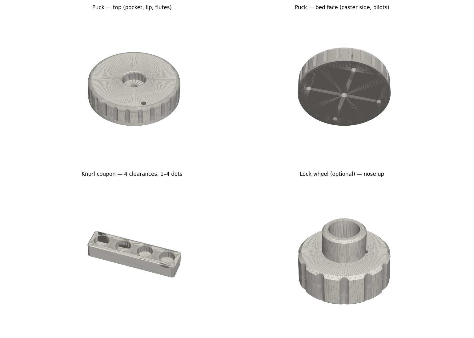
Where it went wrong, usefully. The spec included a little snap lip at the top of the pocket to hold the bolt in, justified with a strain calculation. On the coupon, the bolt would not go into any of the four pockets. The math assumed a ring that could stretch, and a lip cut into solid plastic is not a ring that can stretch. I shaved the lip off with a knife, and the coupon gave a real answer: 0.20 mm clearance was loose, 0.10 worked, and the final pucks went to 0.08, which fits almost perfectly. Three pucks at that number, no more test prints.
Two things came out of that, and they are the habit I would most like you to steal. The fit went into a measured fits table in my printer notes, so the next part starts from 0.08 instead of a guess. And both prompts gained a rule: a press or snap fit is unproven until a coupon tests it, and the detailed design re-checks any calculation it inherits from the spec.
How these were made
They started as one long prompt for a wall mount for my Wi-Fi router, above a kitchen outlet. I gave that same prompt to three different AI models and let each one produce a full CAD package on its own: concept, model, print settings, and a review of its own work.
Then I judged the results by measuring the exported parts, not by reading what each model said about them. Every bridge, every overhang, whether the mesh was even a closed solid. That mattered. One run's instructions said “no supports, do not rotate” over an 89 mm bridge that would have printed into thin air. Its own review had missed it.
The useful finding was not which model won. It was that all three made the same mistakes, and when three different models get something wrong the same way, the problem is the brief.
- All three designed the mount below the outlet first, because I never said where it went. Three full redesigns. Hence: position, size limit and look are asked for up front.
- Models went ahead and modelled concepts I had not agreed to. Hence: a hard stop before any CAD, and a written spec as the only handoff.
- Claims about supports were confident and unmeasured. Hence: no saying anything about supports until the printability table exists.
- One run fixed its geometry, ran out of budget, and shipped a new part with the old part's instructions. Hence: one revision label, and everything regenerated together.
The models did differ. One found constraints nobody had mentioned, one got to a buildable part fastest, one needed the most steering. But that was one part and one run each, which is an anecdote, not a benchmark. The prompt fixes are what held up.
They are built out of mistakes
That was the first round. Almost every rule in these prompts traces to a specific failure, and the end of each file says which. A magnetic photo-album cover that took sixteen revisions, nearly none of them about taste, mostly about a strip of double-sided tape. That history is worth reading even if you never run the prompts. It is also why they are long.
So do the same thing. When something goes wrong, add one line to the prompt saying what to do differently and where the lesson came from. Within a few parts, the prompt knows your printer better than any general advice does.
Make them yours
-
Paths. They assume a
prints/<part-name>/folder per part and aprints/README.md. Rename freely, just keep it consistent. - The printer notes file. Keep it short: printer model and build volume, default slicer profile, the filament you actually have, and a measured-fits table with columns for fit, material, clearance, result, source. Start it empty. It fills in one coupon at a time.
- Your mistakes, not mine. The reference sections at the bottom are my parts. Keep them as examples or delete them. Either way, add your own as they happen.
If you try them, I would love to see what you make. Write to me at me@viyatjhaveri.com, especially if something breaks, since that is exactly how the next rule gets written.
— Viyat